


-135949.jpg)
-135951.jpg)
-135951.jpg)
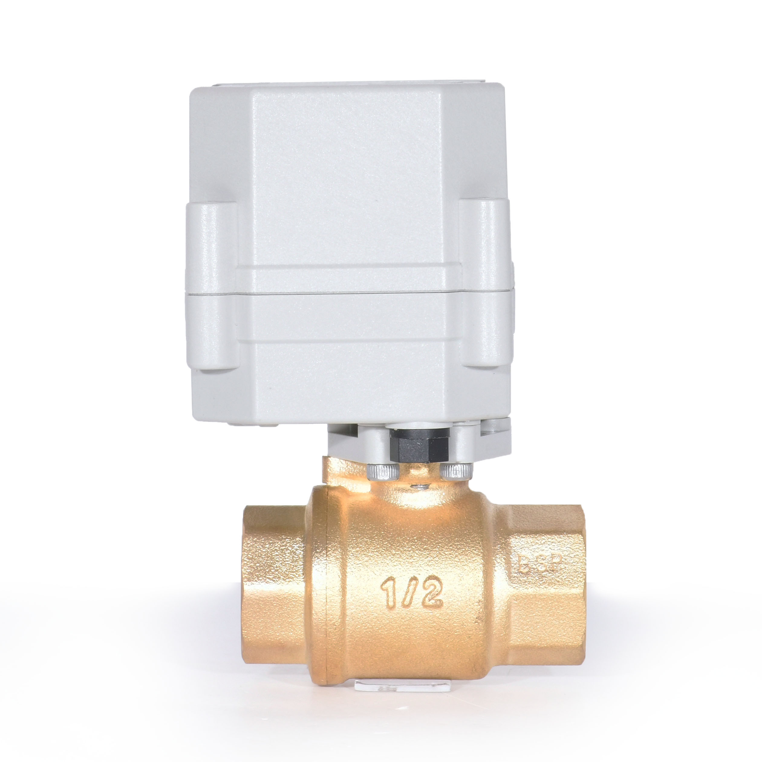
Tonhe A20 SeriesProporational Motorized Ball Valve
1. Analog Iinput Signal:4-20mA 、1-5V 、0-5V 、0-10V、 2-10V、RS485,Output Signal:PWM、4-20mA、 1-5V、 2-10V、 0-5V、 2-10V
2. Beautiful appearance, compact structure, high precision, large output torque, service life is not less than 70,000 times.
3. The actuator and valve can be assembled from multiple angles, which is convenient for users to allocate space.
4. Ball valve adopts floating soft seal structure, no drip leakage, suitable for heavy dirt and long-term no action occasions.
5. Protection grade IP67, can be used in relatively humid environment.
Online Service
Tel:(Export) 86-0576-81100233
(Domestic trade) 86-0576-81100231
Email: tonheflow@china-tonhe.com
WhatsApp: 8617706593558
Fax: 86-0576-81100232


Welcome to our website! Please send your words at any time in the following form and ask us, we will contact you and provide you with the corresponding service as soon as possible. Please write in English.
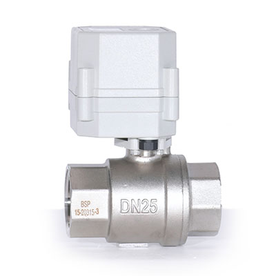
Switch Type - Analog Signal 4-20mA/0-5V/0-10V 3/4" NPT BSP Ball Valve DN20 Stainless Steel Electric Proportional Valve
1. Analog Iinput Signal:4-20mA 、1-5V 、0-5V 、0-10V、 2-10V、RS485,Output Signal:PWM、4-20mA、 1-5V、 2-10V、 0-5V、 2-10V
2. Beautiful appearance, compact structure, high precision, large output torque, service life is not less than 70,000 times.
3. The actuator and valve can be assembled from multiple angles, which is convenient for users to allocate space.
4. Ball valve adopts floating soft seal structure, no drip leakage, suitable for heavy dirt and long-term no action occasions.
5. Protection grade IP67, can be used in relatively humid environment.
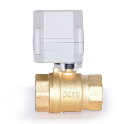
Switch Type - Analog Signal 4-20mA/0-5V/0-10V 1" NPT BSP Ball Valve DN25 Brass Electric Proportional Valve
1. Analog Iinput Signal:4-20mA 、1-5V 、0-5V 、0-10V、 2-10V、RS485,Output Signal:PWM、4-20mA、 1-5V、 2-10V、 0-5V、 2-10V
2. Beautiful appearance, compact structure, high precision, large output torque, service life is not less than 70,000 times.
3. The actuator and valve can be assembled from multiple angles, which is convenient for users to allocate space.
4. Ball valve adopts floating soft seal structure, no drip leakage, suitable for heavy dirt and long-term no action occasions.
5. Protection grade IP67, can be used in relatively humid environment.

Tonhe A20 SeriesProporational Motorized Ball Valve
1. Analog Iinput Signal:4-20mA 、1-5V 、0-5V 、0-10V、 2-10V、RS485,Output Signal:PWM、4-20mA、 1-5V、 2-10V、 0-5V、 2-10V
2. Beautiful appearance, compact structure, high precision, large output torque, service life is not less than 70,000 times.
3. The actuator and valve can be assembled from multiple angles, which is convenient for users to allocate space.
4. Ball valve adopts floating soft seal structure, no drip leakage, suitable for heavy dirt and long-term no action occasions.
5. Protection grade IP67, can be used in relatively humid environment.
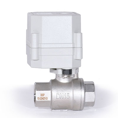
Switch Type - Analog Signal 4-20mA/0-5V/0-10V 1/2" NPT BSP Ball Valve DN15 Stainless Steel Electric Proportional Valve
1. Analog Iinput Signal:4-20mA 、1-5V 、0-5V 、0-10V、 2-10V、RS485,Output Signal:PWM、4-20mA、 1-5V、 2-10V、 0-5V、 2-10V
2. Beautiful appearance, compact structure, high precision, large output torque, service life is not less than 70,000 times.
3. The actuator and valve can be assembled from multiple angles, which is convenient for users to allocate space.
4. Ball valve adopts floating soft seal structure, no drip leakage, suitable for heavy dirt and long-term no action occasions.
5. Protection grade IP67, can be used in relatively humid environment.