


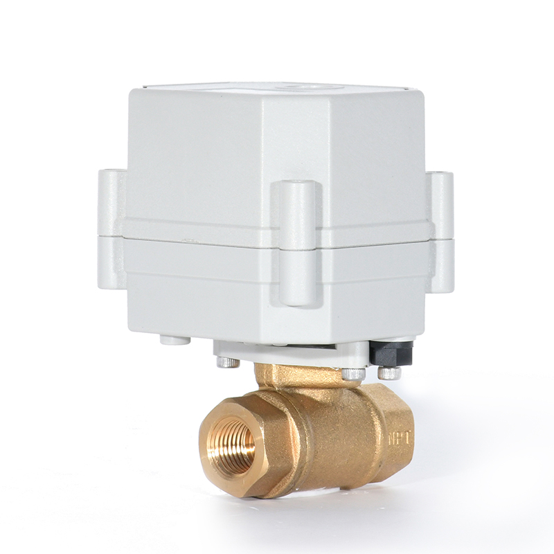
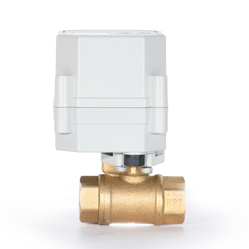
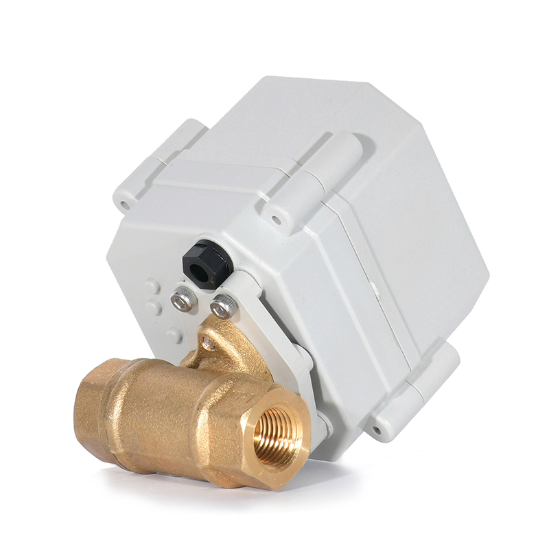
Switch Type - Analog Signal 4-20mA/0-5V/0-10V 1/4" NPT BSP Ball Valve DN8 Brass Electric Proportional Valve
1. Analog Iinput Signal:4-20mA 、0-5V 、0-10V、 2-10V,Output Signal:PWM、 4-20mA、 2-10V
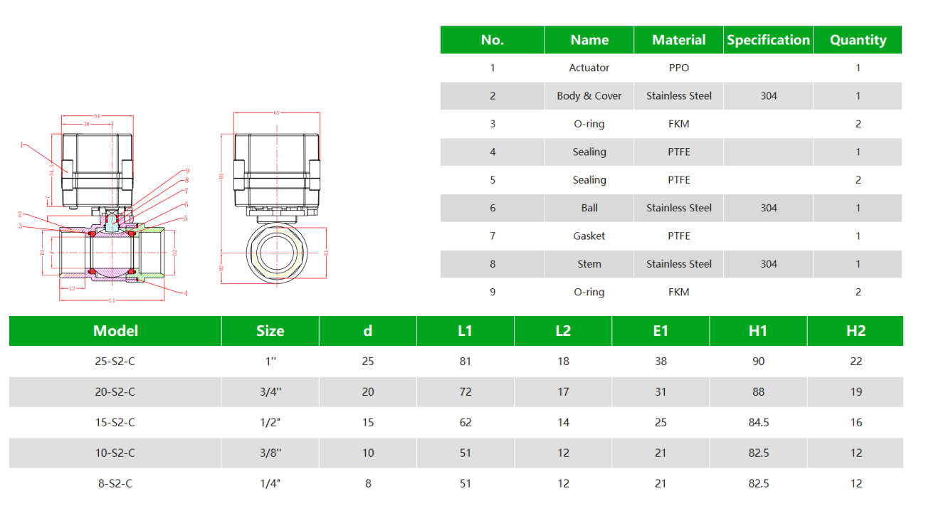
2. Beautiful appearance, compact structure, high precision, large output torque, service life is not less than 70,000 times.
3. The actuator and valve can be assembled from multiple angles, which is convenient for users to allocate space.
4. Ball valve adopts floating soft seal structure, no drip leakage, suitable for heavy dirt and long-term no action occasions.
5. Protection grade IP67, can be used in relatively humid environment.
Online Service
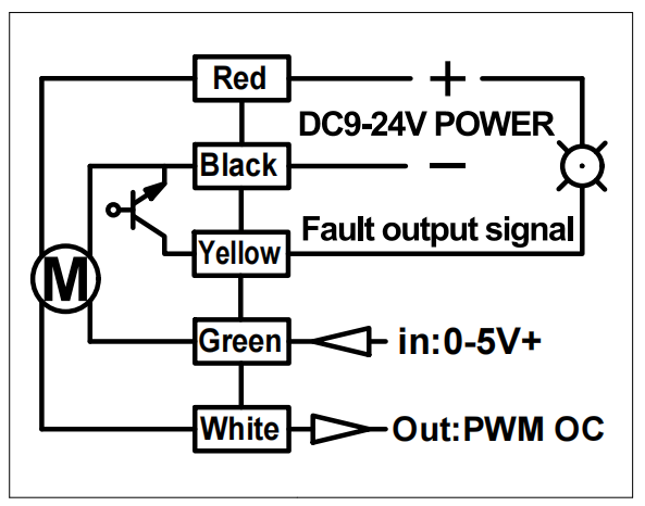
1、RD(red wire) connects to DC9-24V positive pole;
2、BK(black wire) connects to DC9 ~ 24V negative pole, and it is also 4-20mA-/0-5V-/0-10V’s negative pole;
3、GR(green wire) connects to analogy signal positive pole(e.g. 4-20mA, 0-5V, 0-10V) ;
4、YW(yellow wire) connects to ERROR output negative pole. Wet contact NPN triode collector output. When there is an error causing the motor to work with excessive current, such as when debris blocks the valve and the ball cannot rotate, the contact is closed; when working normally, the contact open, it only can pull down the external signal. The load is 500mA
5、WT(white wire) connects to position feedback negative pole.
Wet contact NPN triode collector output, OC output PWM signal, 100Hz, 5%-95%, indicating 0-90 degrees. The load is 500mA.
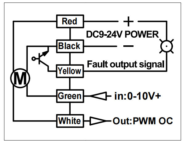
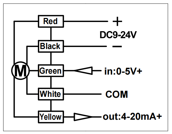
1. RD(red cable) connects DC9-24V positive pole
2. BK(black cable) connects DC9 ~ 24V-negative pole
3. GR(green cable) connects position input /control current +/ control voltage 0-5V
4. WT(white cable) connects common signal
5. YW(yellow cable) connects position feedback positive,output 4-20mA signal
*When output signal is 4-20mA, the biggest input voltage of load resistance is (v-2)/0.02, e.x. power is 15V, (15-2)/0.02=650Ω, suggest to use 300Ω
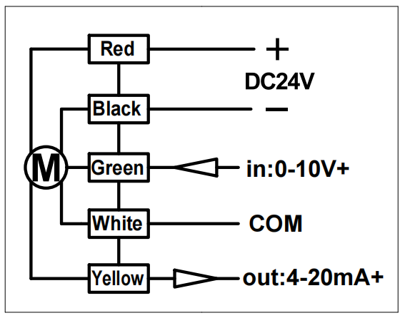
1. RD(red cable) connects DC9-24V positive pole
2. BK(black cable) connects DC9 ~ 24V negative pole
3. GR(green cable) connects position input /control current +/ control voltage 0-10V
4. WT(white cable) connects common signal
5. YW(yellow cable) connects position feedback positive,output 4-20mA signal
*When output signal is 4-20mA, the biggest input voltage of load resistance is (v-2)/0.02, e.g. power is 15V, (15-2)/0.02=650Ω, suggest to use 300Ω
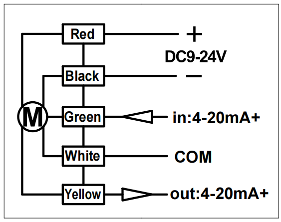
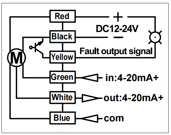
1. RD(red wire) connects to DC9-24V positive pole;
2. BK(black wire) connects to DC9-24V negative pole;
3. GR(green wire) connects to analogy(4-20mA) signal’s positive pole;
4. WT(white wire) connects to negative poles of input analogy signal and output signal
5. YW(yellow wire) connects to position feedback positive pole, output signal 4-20mA is the feedback signal.
* When output signal is 4-20mA, the maximum load resistance is the input power voltage (v-2) /0.02, e.g. if the power is 15V, then (15-2)/0.02=650Ω, it is recommended to use a 300Ω load resistor.
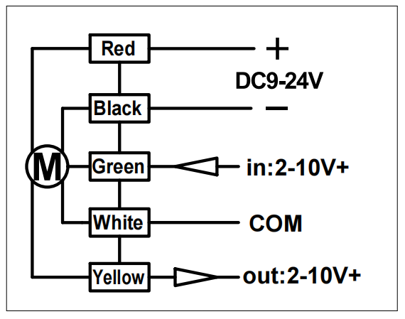
1. RD(red cable) connects DC9-24V positive pole
2. BK(black cable) connects DC9 ~ 24V negative pole
3. GR(green cable) connects position input /control current +/ control voltage 2-10V
4. WT(white cable) connects common signal
5. YW(yellow cable) connects position feedback positive,output 2-10V signal
Welcome to our website! Please send your words at any time in the following form and ask us, we will contact you and provide you with the corresponding service as soon as possible. Please write in English.
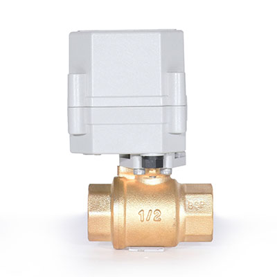
Switch Type - Analog Signal 4-20mA/0-5V/0-10V 1/2" NPT BSP Ball Valve DN15 Brass Electric Proportional Valve
1. Analog Iinput Signal:4-20mA 、0-5V 、0-10V、 2-10V,Output Signal:PWM、 4-20mA、 2-10V
2. Beautiful appearance, compact structure, high precision, large output torque, service life is not less than 70,000 times.
3. The actuator and valve can be assembled from multiple angles, which is convenient for users to allocate space.
4. Ball valve adopts floating soft seal structure, no drip leakage, suitable for heavy dirt and long-term no action occasions.
5. Protection grade IP67, can be used in relatively humid environment.
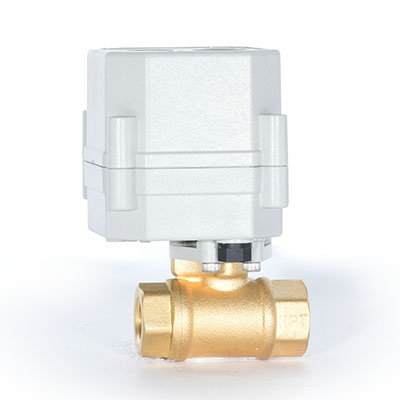
Switch Type - Analog Signal 4-20mA/0-5V/0-10V 3/8" NPT BSP Ball Valve DN10 Brass Electric Proportional Valve
1. Analog Iinput Signal:4-20mA 、0-5V 、0-10V、 2-10V,Output Signal:PWM、 4-20mA、 2-10V
2. Beautiful appearance, compact structure, high precision, large output torque, service life is not less than 70,000 times.
3. The actuator and valve can be assembled from multiple angles, which is convenient for users to allocate space.
4. Ball valve adopts floating soft seal structure, no drip leakage, suitable for heavy dirt and long-term no action occasions.
5. Protection grade IP67, can be used in relatively humid environment.
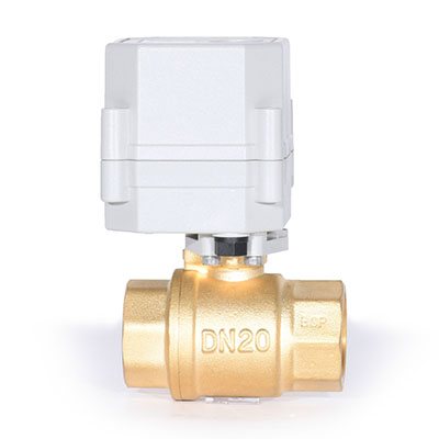
Switch Type - Analog Signal 4-20mA/0-5V/0-10V 3/4" NPT BSP Ball Valve DN20 Brass Electric Proportional Valve
1. Analog Iinput Signal:4-20mA 、0-5V 、0-10V、 2-10V,Output Signal:PWM、 4-20mA、 2-10V
2. Beautiful appearance, compact structure, high precision, large output torque, service life is not less than 70,000 times.
3. The actuator and valve can be assembled from multiple angles, which is convenient for users to allocate space.
4. Ball valve adopts floating soft seal structure, no drip leakage, suitable for heavy dirt and long-term no action occasions.
5. Protection grade IP67, can be used in relatively humid environment.
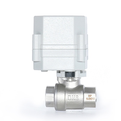
Switch Type - Analog Signal 4-20mA/0-5V/0-10V 1/4" NPT BSP Ball Valve DN8 Stainless Steel Electric Proportional Valve
1. Analog Iinput Signal:4-20mA 、0-5V 、0-10V、 2-10V,Output Signal:PWM、 4-20mA、 2-10V
2. Beautiful appearance, compact structure, high precision, large output torque, service life is not less than 70,000 times.
3. The actuator and valve can be assembled from multiple angles, which is convenient for users to allocate space.
4. Ball valve adopts floating soft seal structure, no drip leakage, suitable for heavy dirt and long-term no action occasions.
5. Protection grade IP67, can be used in relatively humid environment.